
Clip the twisted ends to a reasonable length. End where you started, then twist the beginning and the end together. Give the Sugru something to grip by wrapping the brass wire around the sheathing for a couple of wraps. The downside is that if it needs repair, there will be a bit of work involved and you'll probably need more Sugru to put it back together, but if it's done right, the cable should last quite a while. We can fix this by embedding the whole thing in Sugru. Make sure there is no chance of them coming into contact with each other.Īt this point, the cable and switch will work, but since it's only held together by a few very thin wires, you can tell it's not going to last long. Move the heat shrink over the exposed wires and heat GENTLY with a lighter or the solder iron. It also makes a cleaner joint which is easier to cover with shrink tube. I used to twist the wires together, then tin them as one, but I've been told that this creates a weak point where the wires come out of the sheathing, so I switched to the above method, and it's worked great.

The solder on the wires will melt the two together and form a strong connection.

Align them so the tinned ends overlap completely, then heat one of the wires. Since both ends of the wire are tinned, the way I attach two wires is to put the two ends together, so they are coming from opposite directions. Also make sure it's far enough out of the way that the heat from the solder won't cause it to shrink before it's in place. Slide it down so it doesn't interfere with the soldering. Solder the black wires together Cut a 1/2" section of heat shrink and place it over the black wire. Put a little solder on the two poles where the wires will attach. One red wire will get soldered to the centre pole, and the other goes to one of the ends. Solder the red wires to the switch There are three poles on a SPST switch, a centre pole and two end poles. Clamp the switch in the helping hands to hold it in place. This is done so that the wire can be easily solder to other components or wires. It should melt and distribute to all the strands. Once they're hot, touch the solder to the wire. To tin them, twist the strands together a couple of times, then heat them up with the solder iron. once you do this, take a marker and trace out the pattern of the switch on the panel.Prep the wires Strip the red and black wires on both sections of cable Tin the red and black wires.

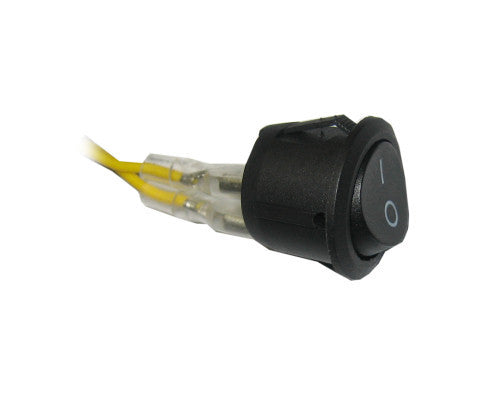
you will want to take the switch and mock it up were you want it on the outer panel. hence the on/off power switch) you will want to have the switch close to the device, so I decided to mount my switch in the metal grated outer panel of my computer.
ON OFF POWER SWITCH PC
the only problem is that the device was so old that it is not compatible with my operating systems boot configuration, causing me to either wait 5-7 mins for my pc to boot when it was plugged in, or I had to unplug the cables every time I rebooted my PC. If you are going to add this switch to an internal device that takes usb (This device uses a 9 pin usb cable, did not have any 9 pin slots left on my motherboard so I made a custom dual usb cable to plug them both in on the out side of my computer.


 0 kommentar(er)
